How to generate a fluorescence compensation matrix for multiplex assays on the naica® system
The naica® system provides a 6-color Crystal Digital PCR™ solution where up to six fluorescence detection channels can be used for high multiplexing capacity and optimal assay design flexibility. When detecting in multiple fluorescence channels, an essential parameter that must be considered and corrected for is fluorescence spillover, which is the overlap of excitation and emission spectra of two or more fluorophores. The Crystal Miner software for the naica® system can be easily used to compute an assay-specific compensation matrix to correct for fluorescence spillover, thus optimizing and ensuring consistent assay analysis. To enable high multiplexing, the naica® system provides a straightforward method to correct for fluorescence spillover through the generation of a compensation matrix.
Why and when to apply a compensation matrix
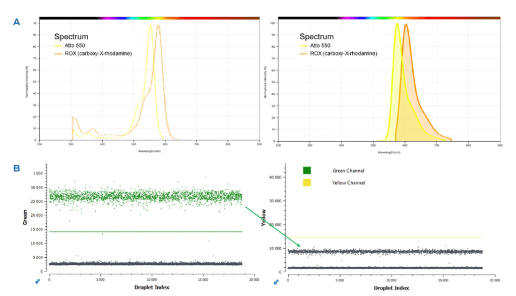
Multiplex Crystal Digital PCR™ employs the use of multiple fluorescently-labelled, sequence-specific probes to detect numerous targets in a single reaction. For example, in a duplex assay, the fluorophores Atto® 550 and ROX display overlapping spectra that can be observed when plotting the normalized fluorescence intensity vs. the wavelength (Figure 1A). Due to the high spectral overlap between these two fluorophores, both will be excited even when trying to illuminate only one, thus leading to highly-overlapping fluorescent signals emitted by both fluorophores (Figure 1A right panel). This overlapping fluorescent signal can be visualized on 1D dot-plots generated by the Crystal Miner software, where the undesired signal coming from the Atto 550 green fluorophore can be visualized in the Yellow ROX channel, as shown by the green arrow (Figure 1B). As the multiplexing level increases, the occurrences of spillover also augment. To enable high multiplexing, the naica® system provides a straightforward way to correct for fluorescence spillover through the generation of a compensation matrix.


How to generate a compensation matrix
To minimize fluorescence spillover in Crystal Digital PCR™, a single run of monocolor controls for each detection channel should be performed when possible. These controls are essential to the generation of a “Compensation Matrix” and must include only positive droplets for each target in each individual detection channel.
Below, the generation of a compensation matrix for a 6-color reference assay is detailed where seven essential controls were performed using in total seven chip chambers (equivalent to two Sapphire chips or one Opal chip). An optional, eighth 6-color control reaction can also be performed to complete the eighth chamber in the Sapphire chip (one Sapphire chip has four chambers whereas one Opal chip has 16 chambers).
The experimental setup was as follows:
- Six monocolor controls in which only the signal specific for a detection channel is present per chamber (Table 1). In these controls, all reagents are present in all chambers except for the target sequences. Individual targets are added one by one to the chamber corresponding to the monocolor control (i.e., only the target detected in blue will be added to the monocolor control for blue, only the target detected in red will be added to the monocolor control for red and so on until each monocolor control is performed). Please see Figure 2, the compensation strategy decision tree, in the case where targets cannot be individually separated
- A No Template Control (NTC) in which no target template is added to determine the negative background fluorescence signal that can emanate from the probes, even in the absence of the target sequences (Table 1).
- An optional control containing a full 6-color reaction containing a signal in all six channels. This control chamber is not needed to generate the compensation matrix but can serve to evaluate the efficacy of the compensation matrix once it is generated.
Stilla Technologies recommends applying the compensation decision tree as a good practice to generate a compensation matrix (Figure 2).


When using automated compensation matrix generation
in the Crystal Miner software, setting up monocolor controls
depends on whether the individual target templates can be
isolated from one another.
If isolating the target templates is not possible, a second strategy is to add all targets but to add only the primer pair to the chamber corresponding to its monocolor control. If primer pairs cannot be isolated, a third strategy is to add all targets and primers but to add only the probe to the chamber corresponding to the monocolor control (Figure 2).
In the case where neither target template, nor primers nor probes are separable, a manual compensation can be performed directly in the Crystal Miner software. For this case, Stilla Technologies recommends consulting the Crystal Miner software User Manual.
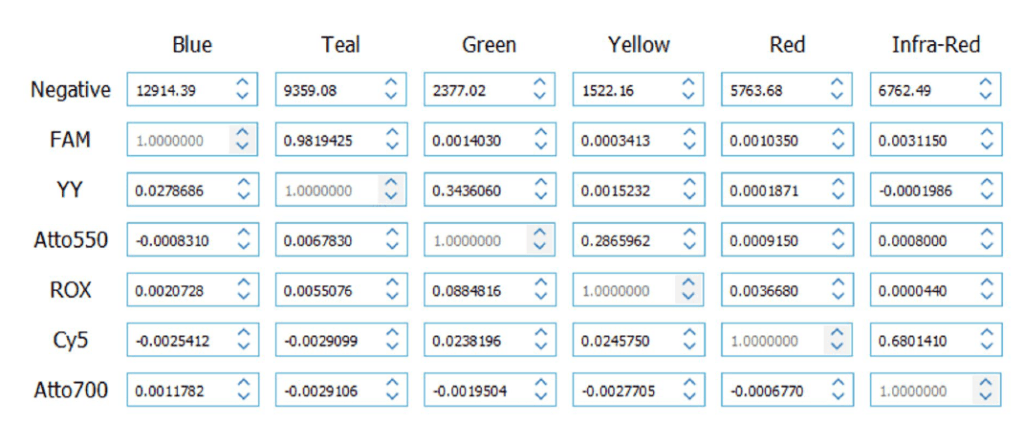
When using the automated compensation matrix generation option, the Crystal Miner software integrates the data generated from the monocolor control experiment and computes the correction factors of the spillover contribution of each fluorophore relative to one other and generates a compensation matrix (Figure 3). To generate an automated compensation matrix, refer to the detailed protocol in the Crystal Miner software User Manual.
Once the color compensation matrix is generated, an exported file (“.ncm” file) can be directly created in the Crystal Miner software and saved.
When performing the same assay on subsequent runs using the same PCR conditions, this same “.ncm” compensation matrix can be imported into the Crystal Miner software and reapplied. In the case of a new assay or when a change to the reaction parameters (for example, change of probe or primer sequence or concentration, or a new PCR program) is made to a previously validated assay, a new compensation matrix specific to the new assay/molecular biology conditions should be generated following the strategy outlined above.
Correct spillover compensation facilitates accurate quantification in Crystal Digital PCR™
As incorrect fluorescence spillover compensation can lead to biases in quantification of the targets of interest of a multiplex assay, spillover must be corrected during data analysis. The naica® system provides a straightforward and user-controlled method to correct for fluorescence spillover through the generation of a compensation matrix.


To better understand the difference between an uncompensated vs. compensated assay, above are examples of 1D dotplot visualization of an uncompensated 6 color reference assay (Figure 4) vs. the same assay compensated (Figure 5) using automated compensation matrix generation. Each target in each color channel is visualized independently, but due to fluorescence spillover, undesired fluorescence signals emanating from adjacent color channels are visible in the uncompensated assay. These undesired spillover signals impede proper thresholding by the Crystal Miner software , thus potentially resulting in false target quantification.
Applying a compensation matrix adjusts the spillover signal coming from the adjacent channels, and consequently allows correct thresholding between the positive and negative clusters and robust quantifications (Figure 5 and Table 2).

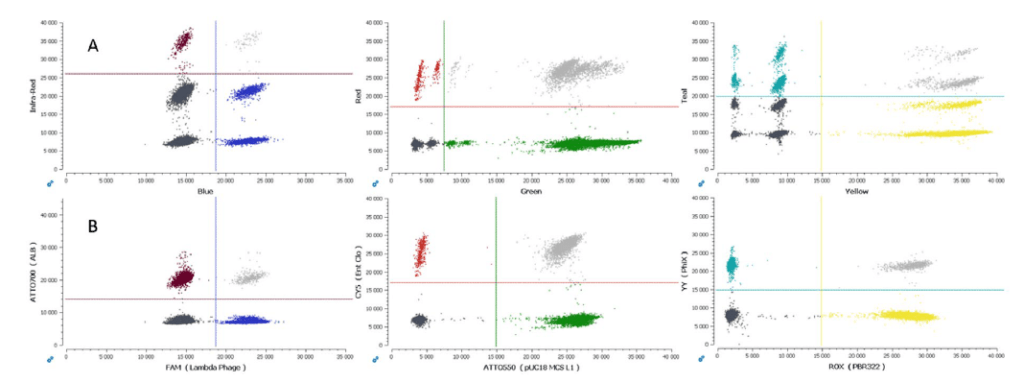
The Crystal Miner software offers a second visualization tool, 2D dot-plots, that allow the user to classify droplet populations as either negative, positive, or double positive. As for 1D dot-plots, correct spillover compensation visualization in 2D dot-plots ensures that droplet clusters are correctly classified, reducing undesired spillover signals that can generate multiple clusters (uncompensated Figure 6A vs. compensated Figure 6B).
Technical Note Highlights
- A fluorescence spillover compensation matrix is mandatory for any Crystal Digital PCR™ multiplex assay to ensure robust and reliable quantification on the naica® system.
- We provide an easy-to-follow and flexible decision tree that should be applied to determine the best strategy to generate a reliable compensation matrix.
- The Crystal Miner software enables automated assay compensation matrix computation for up to six color channels
- Once a compensation matrix has been generated for a given multiplex assay, it can be saved and reused for all subsequent analyses if no major change is made to the assay setup or PCR program.
- By following these guidelines and using Stilla Technologies Crystal Miner software, compensating a multiplex assay is straightforward and reliable.

